Safety Relays

SAFETY RELAYS

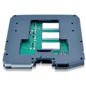
When loads, such as valves or motors, cannot be driven directly by a safety PLC or by an emergency push button, an interposing relay becomes a necessity. As an example, when the power required to switch the load is greater than what can be provided by the PLC or when multiple contacts are required to be driven by the same signal, the use of a relay is a must.

In today’s high integrity applications a standard relay is no longer acceptable. Whether it is for an ESD, F&G, BMS or for any other critical application, a Safety (SIL 3) Relay must be used.

GM International SIL 3 Relays are available in various contact configurations and ratings to cover the majority of applications; they are available with standard DC as well as with AC coils.
Typical applications are shutdown or relief valves control, Fire & Gas valve control, Turbine shut down, AC/DC motors control center, etc.
For each application the specific Safety Function must be determined to select the correct Safety Relay. The Safety Function controls the operating condition of the SIF, therefore of the Safety Relay.

Safety Functions can be basically divided in two main groups:

  • ETS or Energize to Safety or
  • Trip and DTS De-energize to Safety or Trip.
From which there are four operating conditions:

  • NE Relay Coil – NC Relay Contacts ( Load Normally Energized )
  • NE Relay Coil – NO Relay Contacts ( Load Normally De-Energized )
  • ND Relay Coil – NO Relay Contacts ( Load Normally De-Energized )
  • ND Relay Coil – NC Relay Contacts ( Load Normally Energized )

By “NE Relay Coil” we mean a High condition (power on) at the relay coil terminals and by “ND Relay Coil” we mean the exact opposite, a Low condition (power off). NC or NO Relay Contacts determine whether power is available to the load under normal operating conditions or not; with NC contacts the load is Normally Energized and with NO contacts the load is Normally De-Energized.
The Safety Function is to revert the above operating conditions. For example, with NE relay coil and NC relay contacts, DTS Safety Function is to disconnect power to the load by removing power at the relay coil (From High to Low condition); This is the most typical SIL 3 relay function for a NE Load. Or, with a NE relay coil and NO relay contacts, ETS Safety Function is to power-on load by removing power at the relay coil (From High to Low condition).

Other aspects in selecting the safety relay are: the load’s contacts rating; the number of contacts required to be driven by the same control signal; if a single line or both lines of the load must be switched ON or OFF.

For each GMI Safety Relay, a data sheet containing schematics of all possible applications, as well as coil and contacts rating, is available.

SIL-Rated Safety Relays and Informative Safety Manual

SIL Manual: Safety Instrumented System (3rd edition) is now available.

G.M International’s years of experience in safety and electronics has lead to the development of this comprehensive manual on IEC61508 and IEC 61511.

The first two editions have already been of great benefit to engineers, maintenance personnel and whoever wishes to approach the concept of functional safety.

Would you like a paper or electronic copy? Let us know by emailing sales@exloc.com.

D1000 SERIES SIL RELAYS

D1000 Enclosure Characteristics

High channel density result from innovative circuit design using advanced surface mount components.

Plug-in screw terminal blocks to secure termination up to 2.5 mm2

35 mm (Top Hat) DIN-Rail

22.5 mm wide DIN-Rail mounting modules.

  • D1092S    1 channel, Relay Output Module for NE and ND Loads, SIL 3    D1092S Datasheet
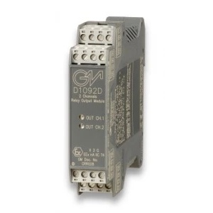
  • D1092D    2 channel, Relay Output Module for NE and ND loads, SIL 3    D1092D Datasheet
  • D1092S-069    1 channel, NE Relay Output Module, SIL 3    D1092S-069 Datasheet
  • D1092D-069   2 channel, NE Relay Output Module, SIL 3   D1092D-069 Datasheet
  • D1093S    1 channel, Relay Output Module for NE and ND loads with diagnostics, SIL 3    D1093S Datasheet

D5000 SERIES SIL RELAYS

D5000 Enclosure Characteristics

High channel density result from innovative circuit design using advanced surface mount components.

Plug-in screw terminal blocks to secure termination up to 2.5 mm2

35 mm (Top Hat) DIN-Rail

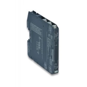
High packing density. Ultra slim 2 channels 12 mm wide.

  • D509oS     5 A SIL 3 Relay Output Module for NE Load    D5090S Data Sheet
  • D5091S     5 A SIL 3 Relay Output Module for ND Load with ND or NE Relay condition    D5091S Data Sheet
  • D5094S    5A SIL3 NE or ND with 2+2 SPST N/O relay contacts connected in parallel and then in series    D5094S Data Sheet
  •  D5094S-104    5A SIL3 Low Voltage Module NE or ND with 2+2 SPST N/O relay contacts connected in parallel and then in series    D9054S-104 Data Sheet
  • D5095S    5A SIL3 NE or ND with 2+2 SPST N/C relay contacts connected in parallel and then in series    D5095S Data Sheet
  •  D5095S-105    D5095S-105  5A SIL3 Low Volt Module NE or ND with 2+2 SPST N/C relay contacts connected in parallel and then in series    D5095S-105 Data Sheet
  • D5290S    10 A SIL 3 Relay Output Module for NE Load     D5290S Data Sheet
  • D5290S-078    5 A SIL 3 Relay Output Module for NE or ND Loads with NE or ND Relay condition D5290S-078 Data Sheet
  • D5290S-079    5 A SIL 3 Relay Output Module (115 Vac coil voltage) for NE or ND Loads with NE Relay condition  D5290S-079 Data Sheet
  • D5290S-080    10 A SIL 3 Relay Output Module for NE Load and 115 Vac coil voltage Din-Rail   D5290S-080 Data Sheet
  • D5290S-084    5 A SIL 3 Relay Out Module (110 Vdc coil voltage) for NE or ND Loads with NE Relay condition  D5290S-084 Data Sheet
  •  D5290-091    10 A SIL 3 Relay Output Module for NE Load and 230 Vac coil voltage    D5290S-091 Data Sheet
  • D5291S    10 A SIL 3 Relay Output Module for ND Load with ND or NE Relay condition     D5291S Data Sheet

D5000 SERIES SMART SIL RELAYS

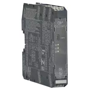
Switching of Safety-Related circuits demands the use of specific SIL certified Relay Output modules, capable of delivering the highest grade of availability and functional safety.
These units are so much more than just a relay; they not only perform the desired safety function, but also provide full Load & Line Internal Diagnostics: load voltage and current, load resistance (patented), leakage from load to earth, coil integrity and internal faults. Moreover, MODBUS communication allows the units to be remotely interrogated and configured.
Hardware is SIL 3 certified, while diagnostic functions are now also SIL 2 certified by TUV: they remain two independent features, which can be used separately or together.

For installation in Zone 2 / Div. 2 Hazardous location. All models are ATEX, IECEx and SIL certified.

  • D5096S    5A SIL3 NO Contact Relay Out Module for NE or F&G/ND with Open/Short Circuit Diagnostic    D5096S Datasheet
  • D5096S-100    SIL3/2 5 A Relay with LFD & Universal Fault Mirror   D5096S-100 Datasheet
  • D509S-106   SIL 3 Relay Low Volt Module for 5 A NE/ND Loads with LFD   D5096S-106 Datasheet 
  • D5097S   5A SIL3 NC Contact Relay Out Module for NE or F&G/ND Load with Open/Short Circuit Diagnostic   D5097S Datasheet
  • D5097S-107   SIL 3 Relay Low Volt Module for 5 A NE/ND Loads with LFD    D5097-107 Datasheet
  • D5293S    4 A SIL 3 Relay Out Module for NE Load with Load and Line diagnostic    D5293S Datasheet
  • D5294S    4 A SIL 3 NO contact Relay Out Module for NE or F&G/ND Load with open/short circuit diagnostic    D5294S Datasheet
  • D5295S    4 A SIL 3 NC contact Relay Out Module for NE or F&G/ND Load with open/short circuit diagnostic    D5295S Datasheet

D5000 SERIES SIL3 LOOP POWERED SWITCH REPEATERS

Switching of Safety-Related circuits demands the use of specific SIL certified Relay Output modules, capable of delivering the highest grade of availability and functional safety.
These units are so much more than just a relay; they not only perform the desired safety function, but also provide full Load & Line Internal Diagnostics: load voltage and current, load resistance (patented), leakage from load to earth, coil integrity and internal faults. Moreover, MODBUS communication allows the units to be remotely interrogated and configured.
Hardware is SIL 3 certified, while diagnostic functions are now also SIL 2 certified by TUV: they remain two independent features, which can be used separately or together.

For installation in Zone 2 / Div. 2 Hazardous location. All models are ATEX, IECEx and SIL certified.

  • D5093S    Single Channel Loop Powered SIL3 24-220 VAC/VDC Transistor-Out Detector    D5093S Data Sheet
  • D5093D    Dual Channel Loop Powered SIL3 24-220 VAC/VDC Transistor-Out Detector    D5093D Data Sheet

HAZARDOUS AREA INSTRUMENTS
BACKED WITH INDUSTRY LEADING SERVICE AND SUPPORT

Download Product and Service Catalogs

Fill out your contact details and we will forward you to download our product brochures. 

HAZARDOUS AREA INSTRUMENTS
BACKED WITH INDUSTRY LEADING SERVICE AND SUPPORT